Hookup Guide
Here you can find wiring diagrams for all configurations the TTL system can be setup to support. As new applications of the system are identified, this section will be updated to reflect all of the possible uses of the system and make setup for the user as easy as possible.
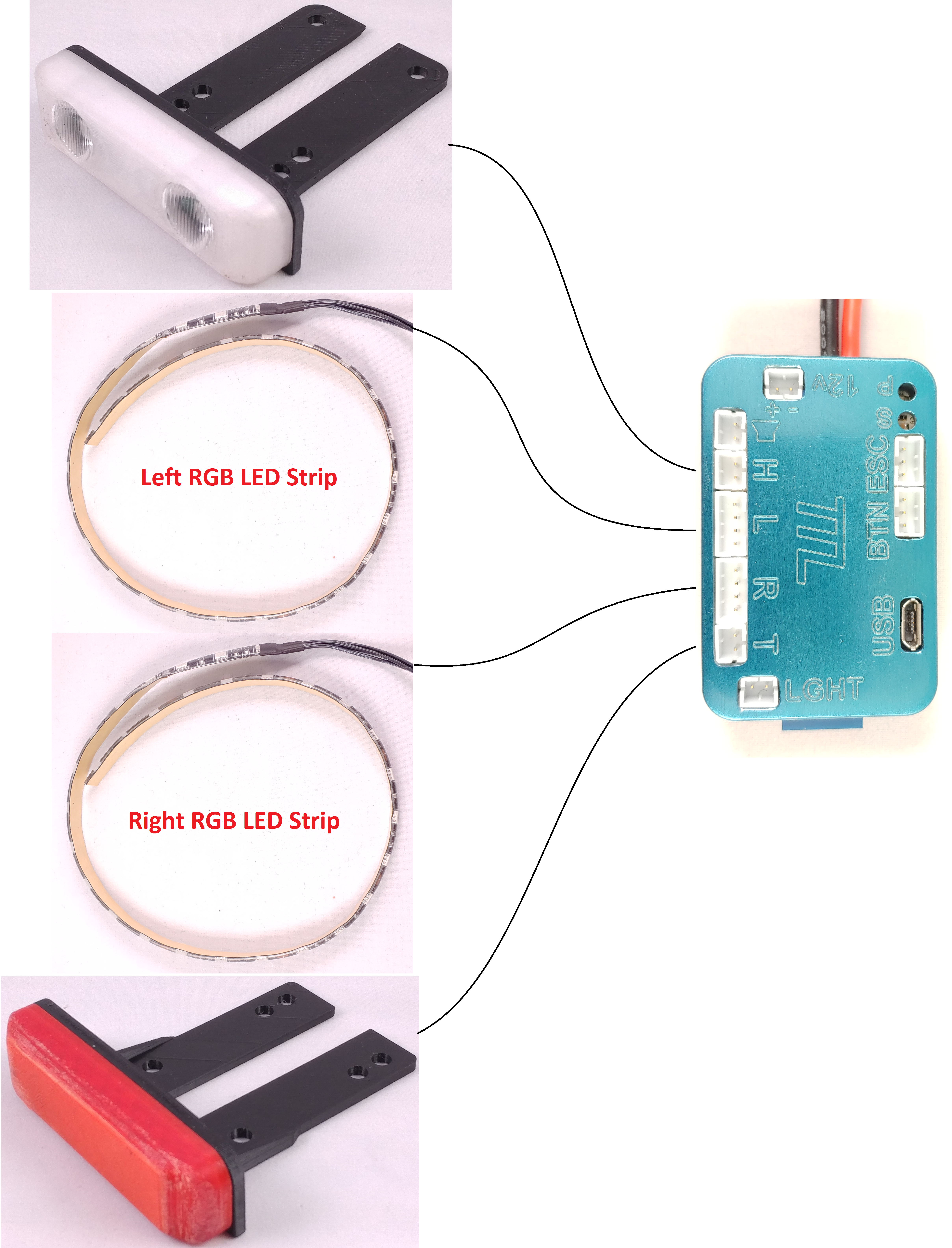
Lights
Below is a diagram that shows how to connect the headlight, side lights, and tail light to the control module.

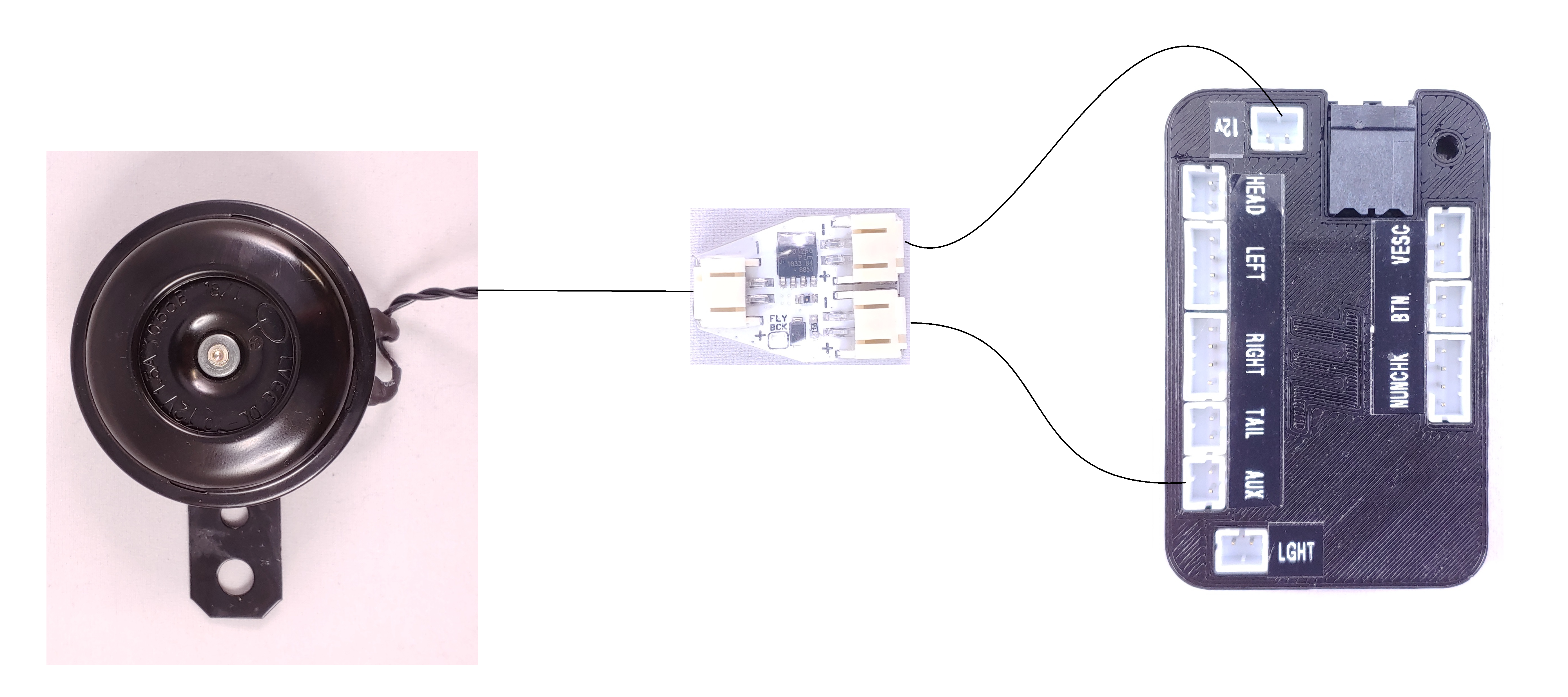
Horn
Below is a diagram that shows how to connect the HPCM with a horn to the control module.

Compatible and Tested Remotes
The list below has been created based on remotes that were tested by users of the TTL system. It is not an exhaustive list of all remotes on the market that may work with the TTL system. The key feature required for a remote to be compatible with the TTL system is having a button that controls an output on the receiver in either a momentary or toggled fashion. Remotes with momentary buttons will have access to more functionality when controlling the TTL system than toggled buttons.
- Torque Boards Nano
- Torque Boards Mini
- Alien Power Systems
- Enertion Nano-X
- Feather based Remotes (with custom FW)
- Hobby King GT2B
Remote Reciever
Below is a diagram that shows how to connect the reciever of a PWM (“PPM”) based remote (TB Nano, HK GT2B, ect.) to the button port of the control module.

Power
Caution! Before connecting the ESC UART cable, it is important to make sure the TTL control module powers up at the same time as the ESC. If the ESC UART cable is connected, the TTL is powered, and the ESC is unpowered, damage may occur to the ESC.
Below are diagrams outlining the different ways to connect power to the control module.
To power the externally powered (EP) control module, a 12v buck convert needs to be connected between the battery and the control module.
 Below shows how to connect the Universal Power Switch (UPS) in series with the EP control module’s power feed to allow the FOCbox Unity to switch power on/off. More information on the UPS can be found in its own section below.

Below shows how to connect the Universal Power Switch (UPS) in series with the SP control module’s power feed to allow the FOCbox Unity to switch power on/off. More information on the UPS can be found in its own section below.

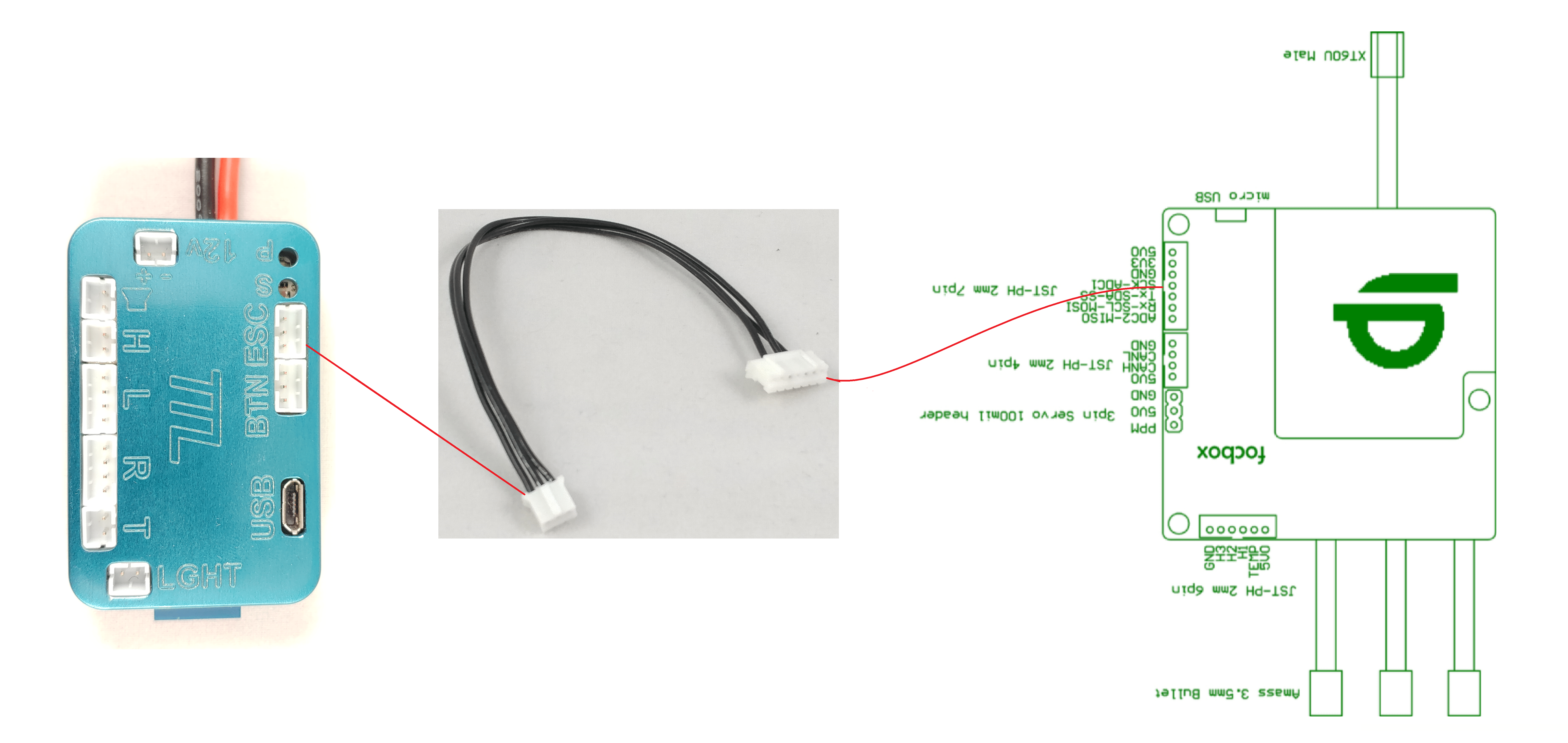
ESC
Below are diagrams for hooking up the control module to a VESC v4.12 HW based ESC, FOCbox, and FOCbox Unity. Also included is a pinout for the ESC-Side of the ESC adapter cable.
For Dual ESCs (or more) setups, the ESC adapter cable should be plugged into the ESC with the remote connected. This is important for builds using PWM (PPM) remotes. If the TTL system is not connected to the master ESC, it will not be able to read the throttle values and perform dynamic brake lights.

RF Remote
The RF Remote connection was designed to be as simple as possible. There are two connectors attached to the remote’s receiver: one with two pins and the other with three. Plug the two pin connector into the “12v” port of the TTL control module, and plug the three pin connector into the “BTN” port.
Control Module Details
The TTL Control Module is the brain of the TTL System. The headlights, tail lights, side lights, and aux output are all controlled by this module. Two versions of the control module are available; The Self Powered (SP) version and the Externally Powered (EP) version. The differences between both versions are describred below.

OUTPUTS
Horn: Output used to control a 12v horn. This output is intended to be used with a 12v 1.5A horn.
Head: Ouput used to control the headlights
Left: Ouput used to control the RGB LEDs on the left side of the eboard
Right: Ouput used to control the RGB LEDs on the right side of the eboard
Tail: Ouput used to control the tail lights
INPUTS
Light: Input for a photoresistor that is used by the control module to turn on/off the lights bases on light level of the environment. This feature is not yet implemented.
Button: Input for the button channel of a PPM based remote. This is typically the second channel on the reciever.
COMMS
ESC (UART): The ESC comm port is used to connect to a VESC based motor controller. The TTL uses this connection to read information from the ESC to create unique lighting effects and display real time data on the mobile app.
SP Control Module
This version of the TTL Control Module uses an onboard DC/DC converter to step the input voltage (20-50v) down to 12v for use with the lights and control logic. This version is meant to make the TTL System as compact as possible while providing all of the core functionality.
SPECS:
- Input Voltage: 20 – 50v
- Max Power Output: 30W (includes control logic)
- Power Connector: Male XT30
- All Light Outputs: 12v @ 2.5A max*
- Comms: Bluetooth 4.0 to Phone, UART to VESC
- # of Controlled LED Channels: 9
- Inputs: Light Sensor, Remote Button
* Max current is total current of all outputs. Each output is capable of handling 2.5A by itself, but the 12v regulator can only supply 30W.
EP Control Module
This version of the TTL Control Module allows the user to power the lights and control logic using a 12v power source of their choosing. The typical source would be a 12v Step Down Converter that is compatible with the eskate’s battery voltage and capable of sourcing enough current for the lights intended to be used.
SPECS:
- Input Voltage: 12v @ 10A max
- Power Connector: 16-24 AWG Screwless Terminal Block
- All Light Outputs: 12v @ 3A max*
- Comms: BLE, I2C to VESC, I2C to Wii Nunchuck Controller
- # of Controlled LED Channels: 9
- Inputs: Light Sensor, Remote Button
* Max current is that of a single ouptut channel. The max total output current is determined by the 12v power supply use.
Reprogramming a Module
There are two options for updating the firmware of a TTL control module, wirelessly through the android app, or using the built-in USB port. Follow the instructions below to update the Control Module using the USB port. Before starting make sure you have downloaded the BOSSA tool and the latest TTL FW from here.
- Make sure module is powered off
- Connect USB cable between module and PC (The USB cable is used for data only, it does not power the module)
Using BOSSA (use this one)

- Run BOSSA the flash programming utility
- Select the comm port that the control module is connected to
- Open the latest .bin file
- Set the write options to “Erase all”
- Set the Flash Offset field to “0x2000“
- Press “Send File”
- If no error, you are done. In case of an error, contact support@solidcircuits.net
Using SAM-BA Tool (available as buck-up if BOSSA doesn’t work)

- Run SAM-BA Monitor 2.15
- Select the comm port that the control module is connected to (should be automatic)
- Select the “samd21_xplained_pro” board

- Change address under Flash tab to “0x2000“
- Open latest .bin file in the “Send File Name” field
- Set script to “Erase application area” and click “Execute”
- Press “Send File”
- If no error, you are done. In case of an error, contact support@solidcircuits.net
Universal Power Switch (UPS)
The Universal Power Switch (UPS) is a component that allows the user to wire the TTL system to an ESC with an integrated power switch. When installed, the UPS will turn the TTL system on/off based on the on/off state of the ESC. This makes for much cleaner and convenient builds when using ESCs like the the FOCbox Unity, BKB Xenith, or Flipsky Dual 6.0 ESC.
The UPS controls the load’s on/off state based on the voltage seen at the pins of the JST connectors. The JST connectors serve as a pass through to allow a voltage monitor to be connected in series.
Universal Power Switch Specs:
- Control Voltage: 12v – 60v
- Switched Voltage: 0 – 60v
- Load Current: 2.5A
Head and Tail Lights
The head and tail lights were specifically designed to be used with the TTL system. They are powered by 12v DC and have a low current draw to allow for use with the SP version of the Control Module.
Headlight Specs:
- Voltage: 12v
- Current: 170mA
- Lumens: ~300lm
Tail Light Specs:
- Voltage: 12v
- Current: 110mA
A2D Module Details
The A2D Module is an adapter that allows the TTL Control Module to control addressable LED strips from each of the side light ports. Once connected to the TTL control module, the mobile app can be used to configure all settings for the digital strips. The types of digital RGB LED strips supported by the A2D module are APA102 and SK9822.

Usage
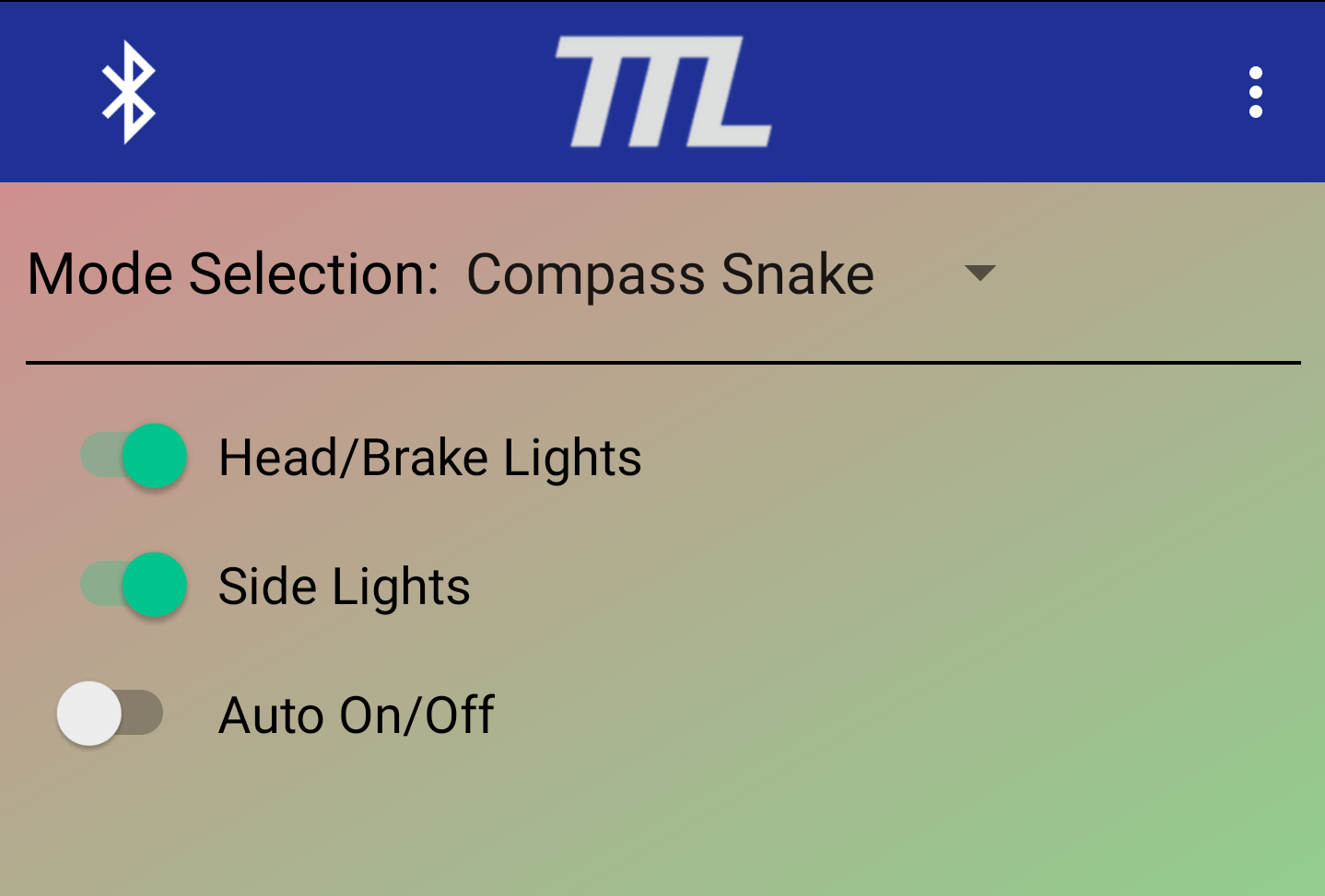
EXPLAINATION OF LED MODES
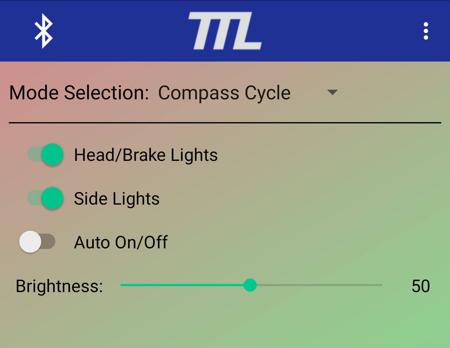
General LED Mode Options
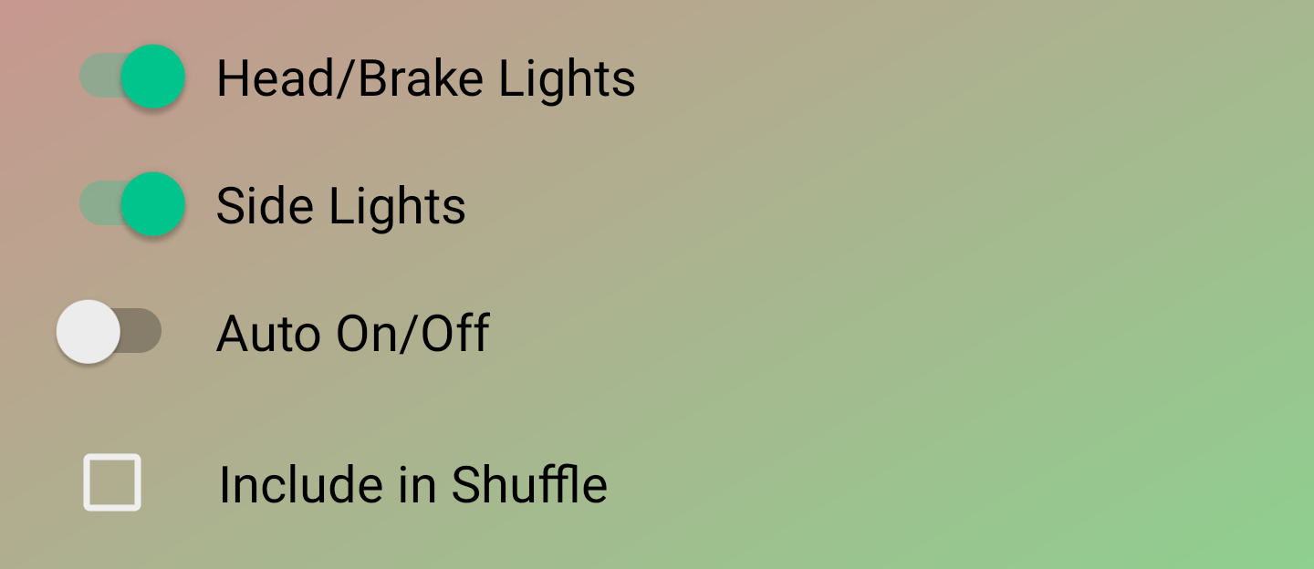
* Head/Brake Lights: Controls the on/off state of the head and tail lights
* Side Lights: Controls the on/off state of the RGB side lights
* Auto On/Off: When this option is selected, the lights will automatically turn off when the board is picked up
* Include in Shuffle: When checked, the currently selected mode will be included in the list of modes that is shuffled between every 30s when light mode shuffling is enabled. Light mode shuffling can be enabled in the “Configure Lights” menu.
– Read Current Settings: Reads the mode values stored on the TTL Control Module into the app
– Apply: Applies the LED mode values configured in the app to the TTL Control Module
Analog LED Modes
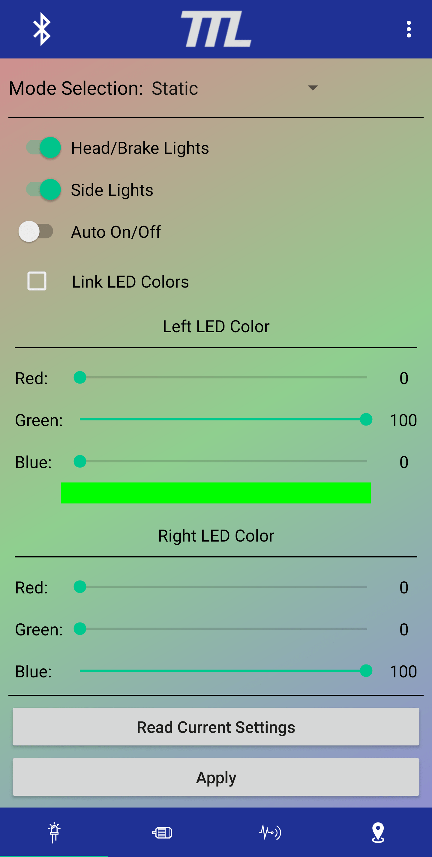
– Static: Side LEDs are set to specific colors that do not change
Left LED Color
* Red: Sets the brightness of the left red LEDs
* Green: Sets the brightness of the left green LEDs
* Blue: Sets the brightness of the left blue LEDs
Right LED Color
* Red: Sets the brightness of the right red LEDs
* Green: Sets the brightness of the right green LEDs
* Blue: Sets the brightness of the right blue LEDs

– Color Cycling: Side LEDs cycle through all colors of the color wheel
* Cycle Rate: Sets the speed at which the side LEDs cycle through the color wheel
* Brighness: Sets the brightness of the side LEDs
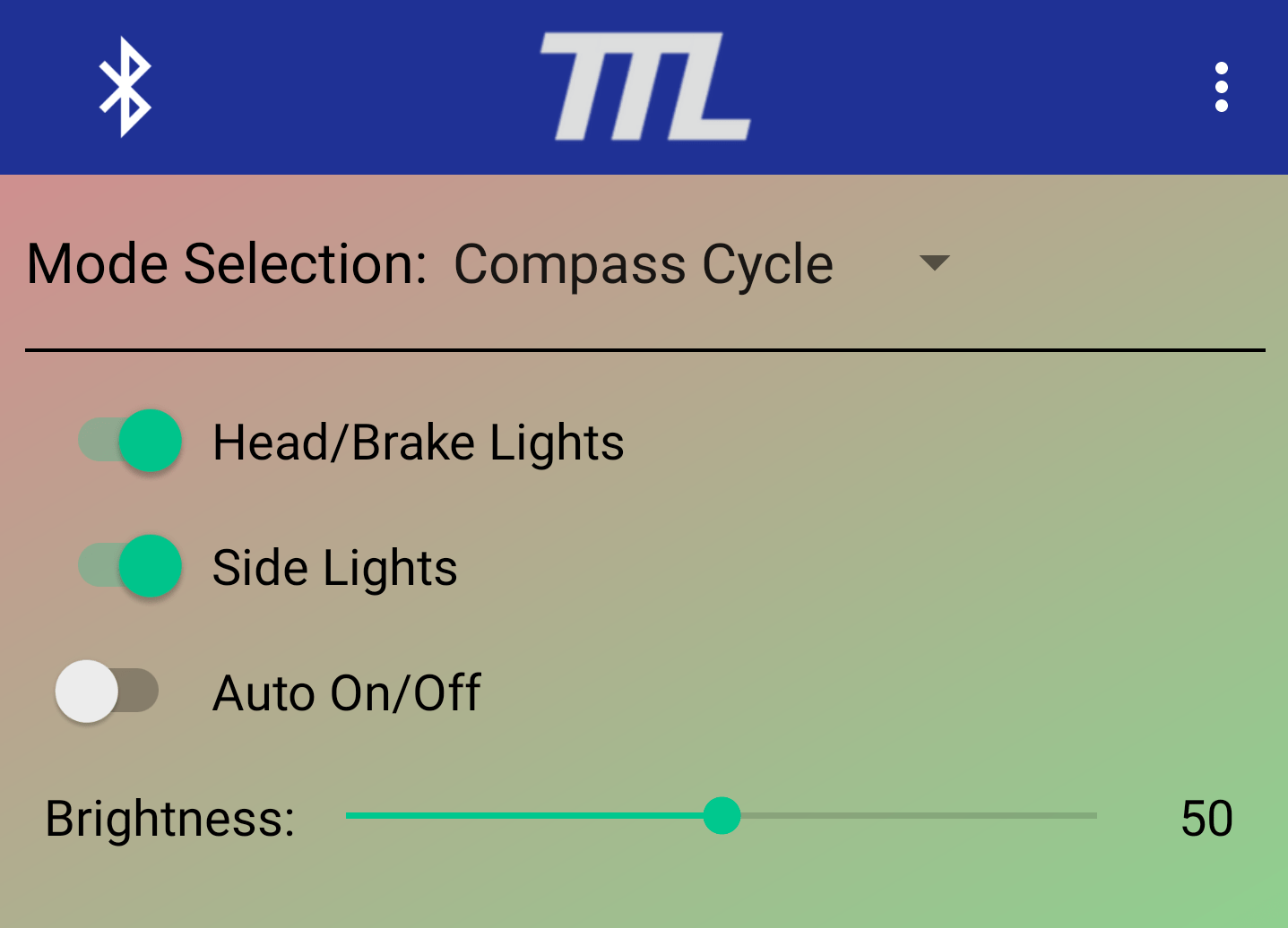
– Compass Cycle: Side LEDs’ color is set based on the direction the board is facing
* Brightness: Sets the brightness of the side LEDs

– Throttle Based: Side LEDs’ color is set based on the position of the remote’s throttle
* Sensitivity: Sets how quickly the LEDs’ color changes
* Brightness: Sets the brightness of the LEDs
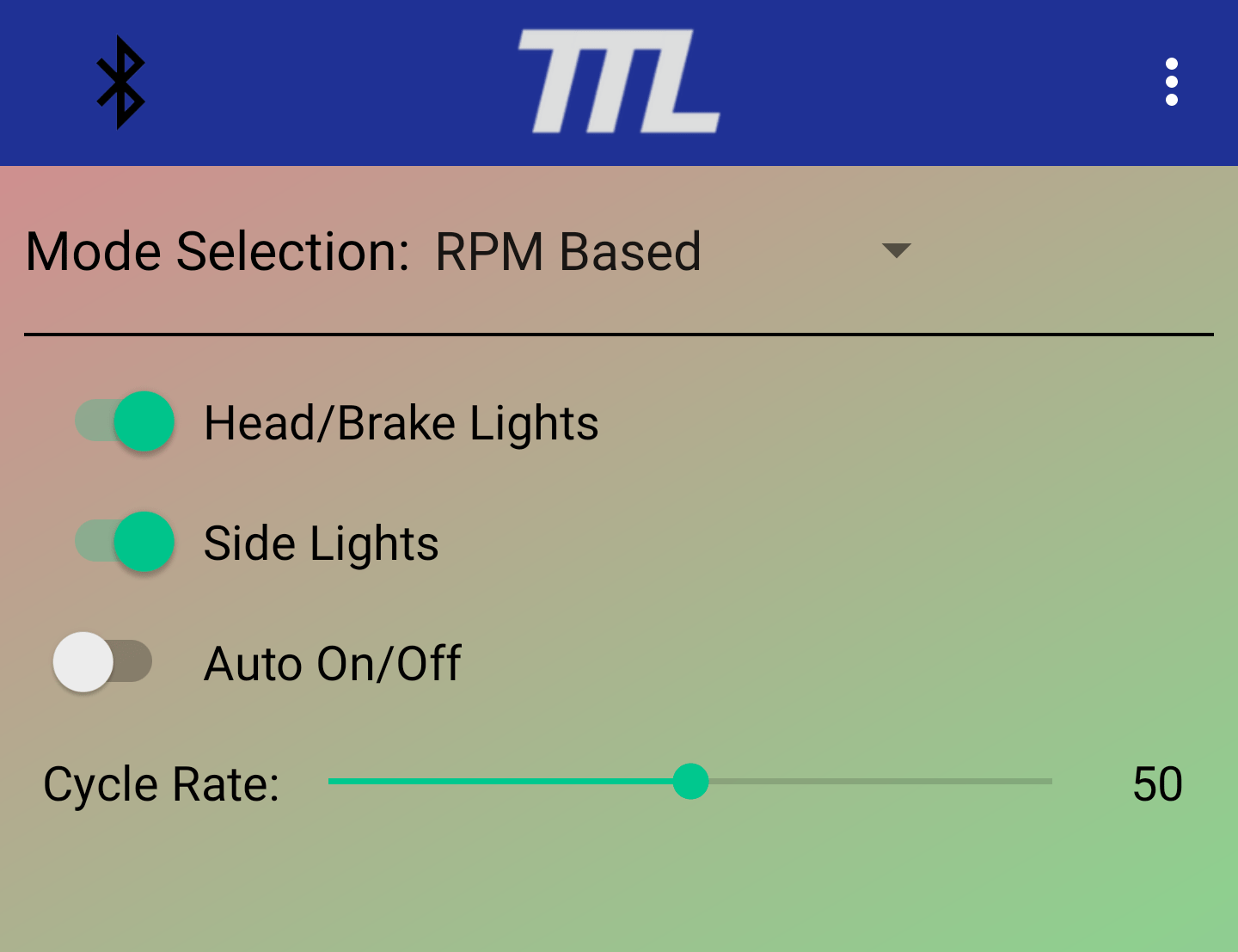
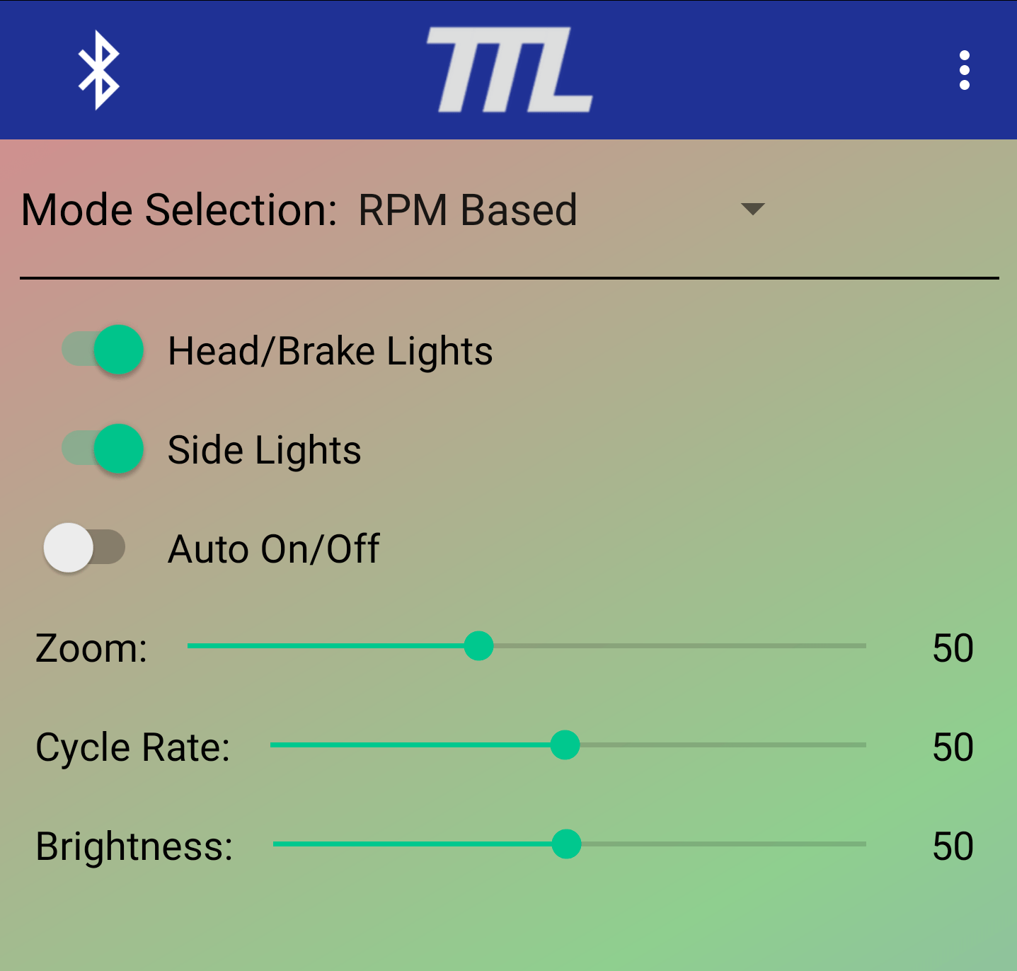
– RPM Based: Side LEDs’ brightness is set based on on the RPM of the motor while their color cycles through the color wheel. The ESC’s Max/Min RPM settings are used as the scale
* Cycle Rate: Sets the speed at which the side LEDs cycle through the color wheel

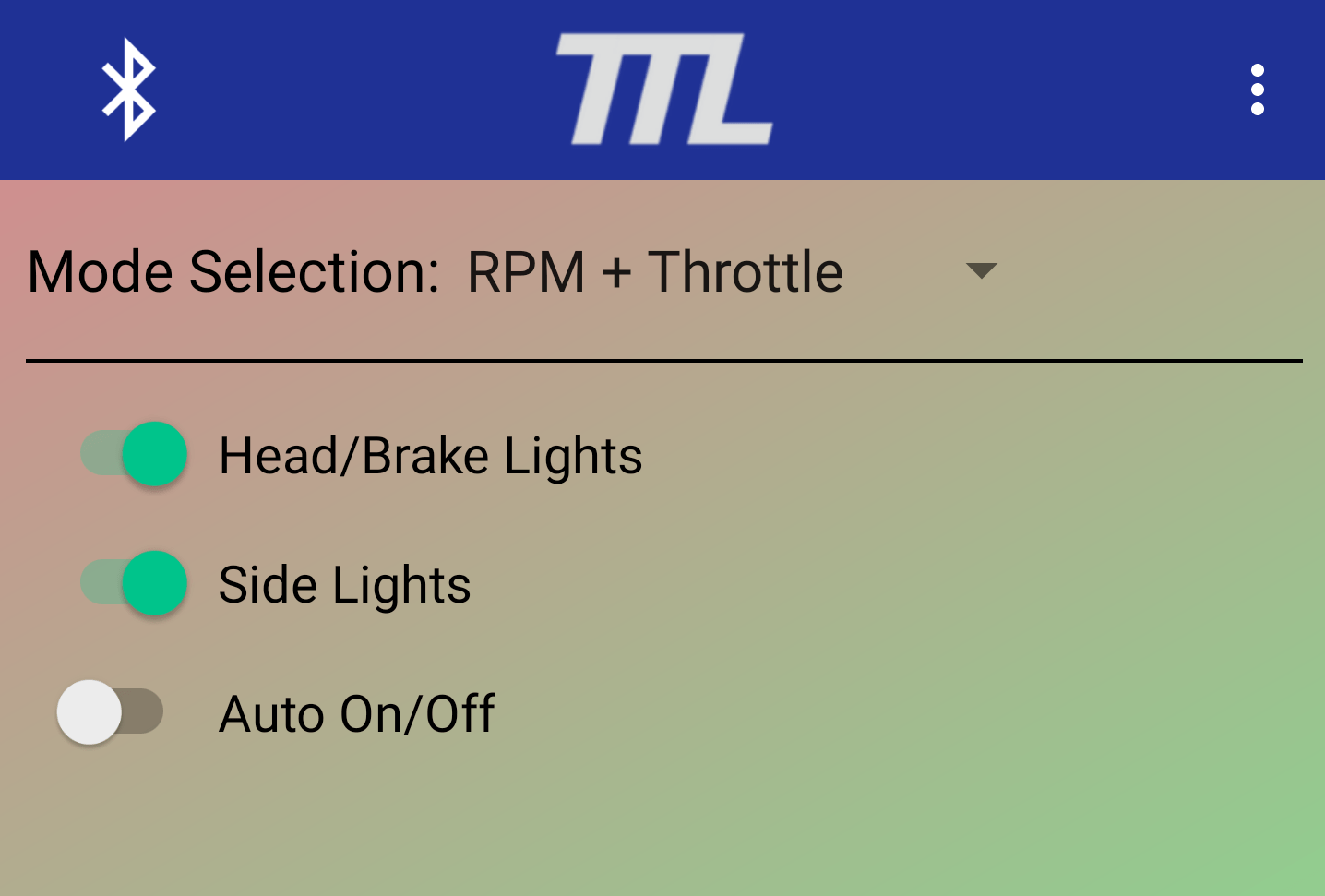
– RPM + Throttle: Side LEDs’ brightness is set based on on the RPM of the motor while their color is set by the position of the remote’s throttle. The ESC’s Max/Min RPM settings are used as the scale.

– X Accel Based (Splash Carve): Side LEDs’ brightness is set based on the amount of acceleration the IMU experiences along it’s X axis (left to right of board).
* Cycle Rate: Sets the speed at which the side LEDs cycle through the color wheel

– Y Accel Based: Side LEDs’ brightness is set based on the amount of acceleration the IMU experiences along it’s Y axis (front to back of board).
* Brightness: Sets the brightness of the LEDs
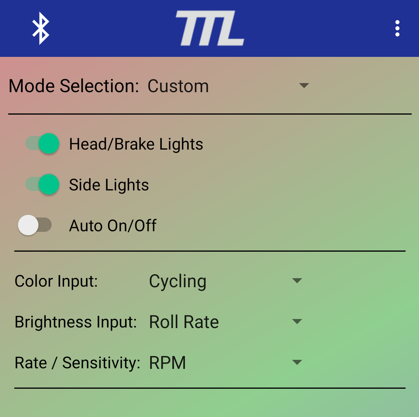
– Custom: Allows user to select the basis of the side LEDs’ color and brightness
* All methods outlined above, along with other, are available for creating a custom lighting mode
* Due to the large number of option available in this mode, the basis inputs will not be described here
* Experiementation with the differnt color and brightness basis’ is required for full understanding of this mode
Digital LED Modes
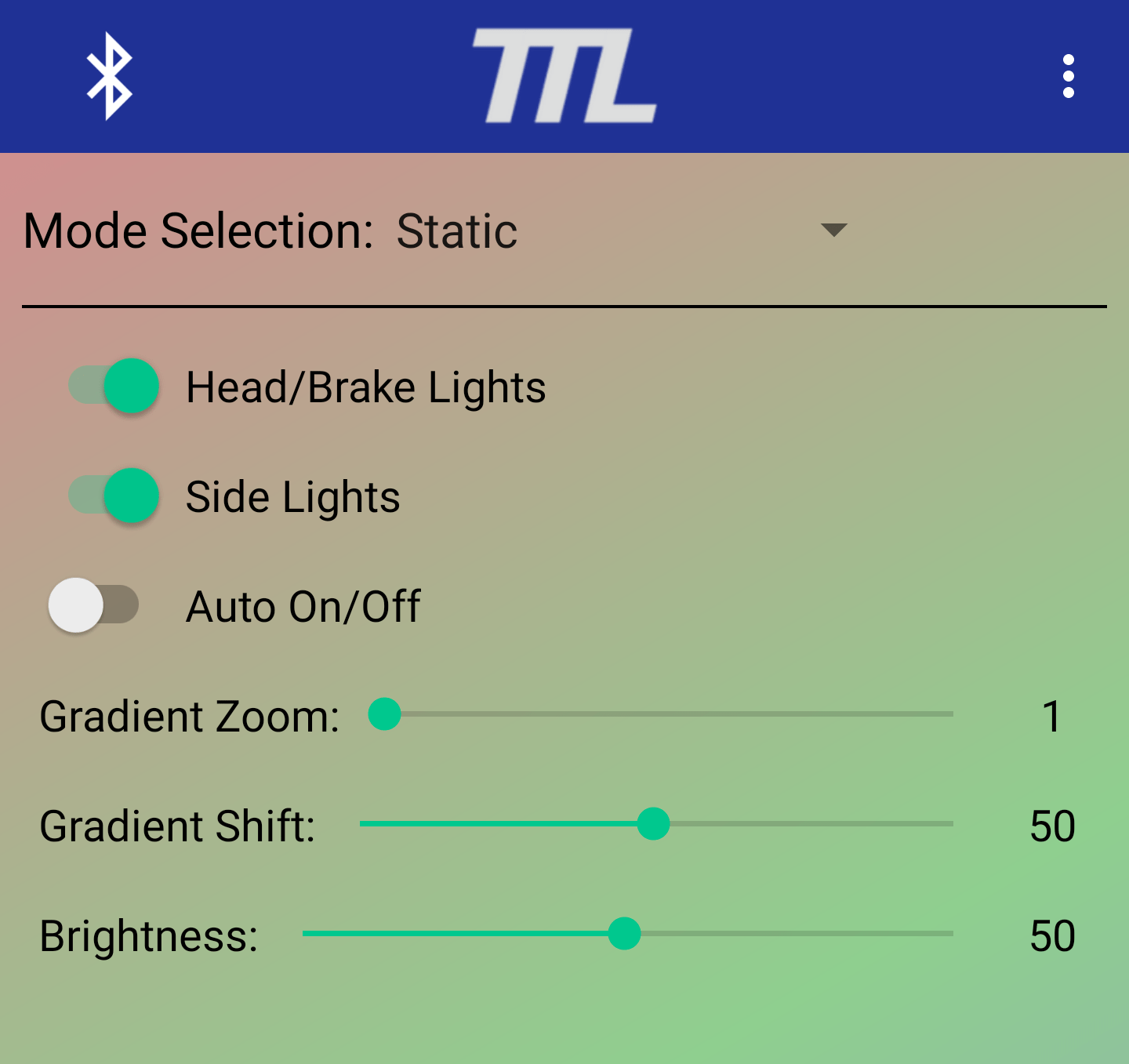
– Static: Side LEDs are set to specific colors that do not change
* Gradient Zoom: Sets how aggressive or gradual the color gradient is
* Gradient Shift: Sets the position along the color gradient that is being displayed
* Brightness: Sets the brightness of the RGB LEDs.

– Skittles: Side LEDs are randomly and individually set to unique colors multiple times a second
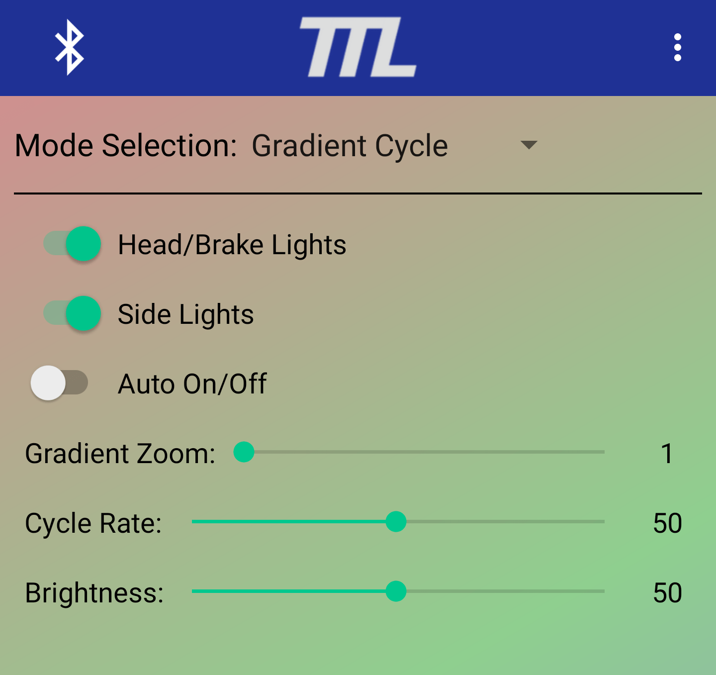
– Gradient Cycle: Side LEDs cycle through a color gradient that can be modified with the options below
* Gradient Zoom: Sets how aggressive or gradual the color gradient is
* Cycle Rate: Sets how quickly the LEDs cycle through the color gradient
* Brightness: Sets the brightness of the side LEDs
– Compass Cycle: Side LEDs’ color is set based on the direction the board is facing
* Brightness: Sets the brightness of the side LEDs

– Throttle Based: Side LEDs’ color is set based on the direction the position of the throttle
* Gradient Zoom: Sets how aggressive or gradual the color gradient is
* Gradient Shift: Sets the position along the color gradient that is being displayed
* Sensitivity: Sets how quickly the LEDs cycle through the color gradient when the throttle is moved
* Brightness: Sets the brightness of the side LEDs
– RPM Based: Side LEDs’ color is based on a color gradient that is cycled through at a rate proportional to the motor RPM.
* Zoom: Sets how aggressive or gradual the color gradient is
* Cycle Rate: Sets the speed at which the side LEDs cycle through the color gradient
* Brightness: Sets the brightness of the side LEDs
– RPM + Throttle: Description coming soon
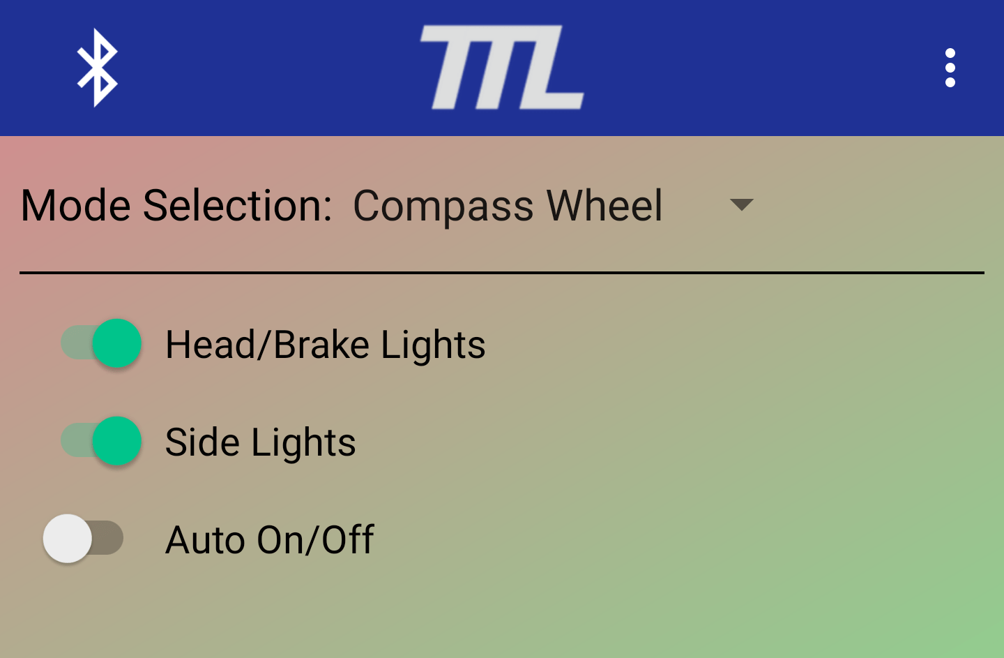

– Compass Wheel: Description coming soon
– Compass Wheel: Description coming soon
EXPLAINATION OF MOTOR INFO SCREEN

– Live Graph: Shows a plot of the various values reported by the ESC. The values displayed are controlled using the check boxes below
– Motor Stats: These fields show the last value reported by the ESC. When the check box next to a given value is checked, THat value is displayed on the graph above
– Log Enable Button: This toggle button controls whether or not the motor stat values are stored in the data log or not. THis button will only appear if logging is enabled in the settings menu.
EXPLANATION OF SENSOR INFO SCREEN

– Live Graph: Shows a plot of the various sensor measuremnts gathered from the IMU along with the throttle values of the connected remote. The values displayed are controlled using the check boxes below.
– Sensor Measurments: These fields show the last value read from the IMUs sensors and the connected remote.
– Log Enable Button: This toggle button controls whether or on the the IMU sensor values and remote throttle are stored in the log or not. This button will only appear if logging is enabled in the settings menu.
EXPLAINATION OF THE MAP SCREEN
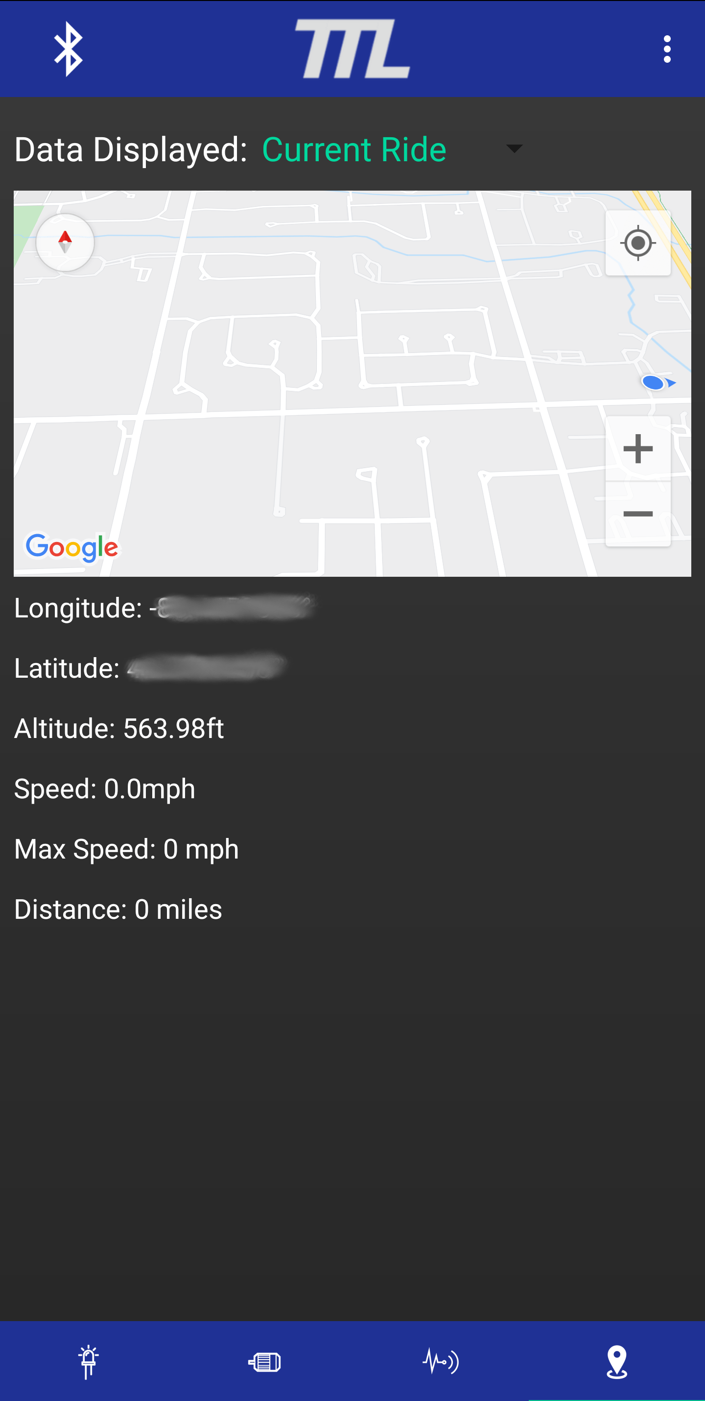
– Data Displayed: This part option is not implemented yet. Currently, only the data collected since opening the app will be displayed.
– Map: Displays rider’s current location and shows the rider’s path. The path will only be drawn whe the wheels of the eboard are spinning.
– Longitude: The longitude of the rider’s last reported position.
– Latitude: The latitude of the rider’s last reported position.
– Altitude: The altitude of the rider’s last reported position.
– Speed: The speed the rider is curreenly goingas reported from google maps.
– Max Speed: The top speed the rider reached during the current trip.
– Distance: The total distance of the riders trip. This value only includes the distance traveled on the eboard.
– Log Enable Button: This toggle button controls whether or on the the map data is stored in the log or not. This button will only appear if logging is enabled in the settings menu.
EXPLAINATION OF MAIN MENU
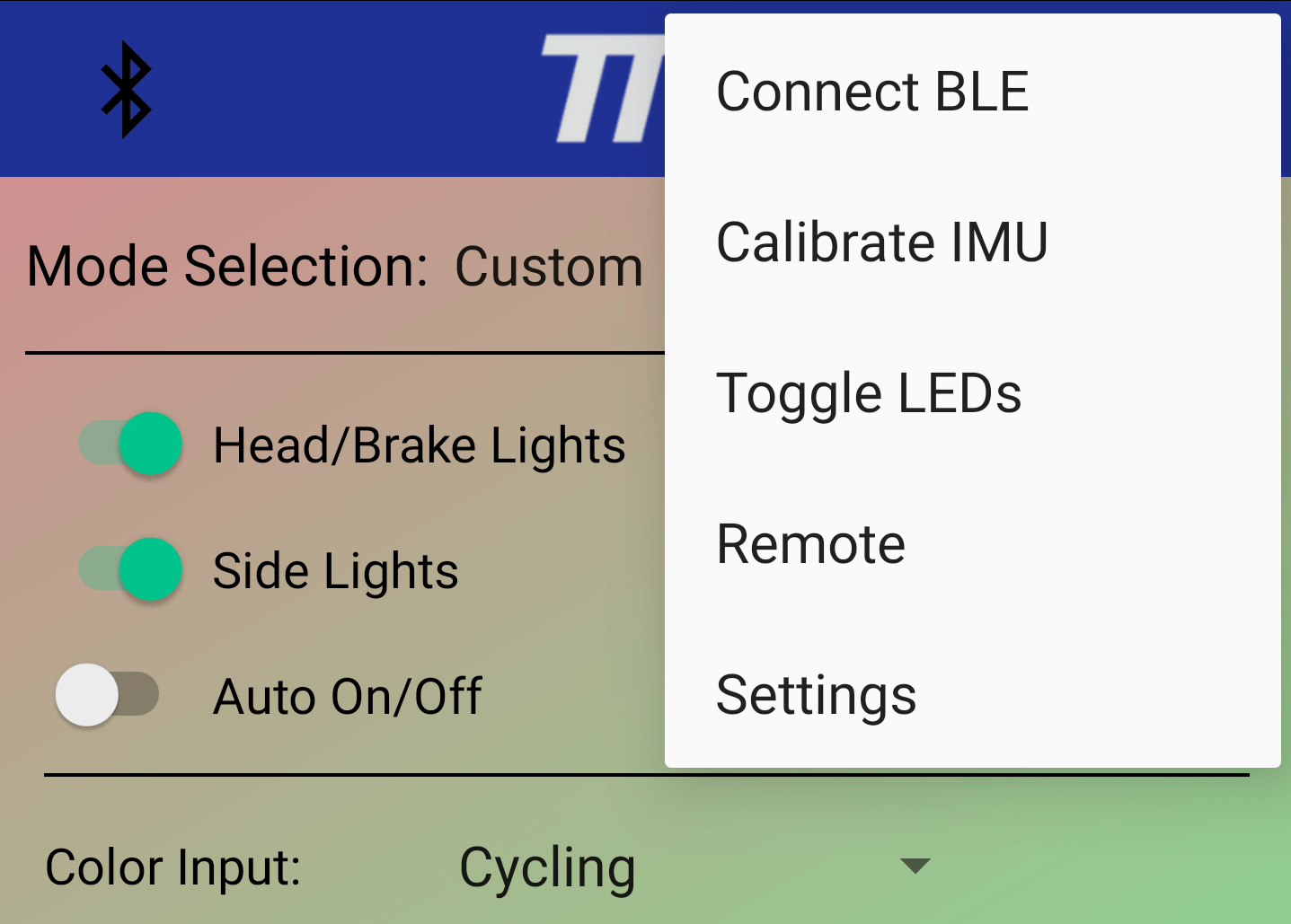
– Start/Stop Logging: This option is displayed only if logging is enabled in the app settings. Allows the user to start/stop collecting a log of all data selected in the main menu. This log will be stored in the TelTail folder in the top level internal storage location. This feature was added for development purposes and will not be used by most users. To remove all logging related options from view, please refer to the Data Logging Configuration section.
– Dis/Connect BLE: Allows the user to Dis/Connect from/to the TTL Control Module.
– Calibrate IMU: Allows the user to calibrate the IMU
– Toggle LEDs: Allows the user to turn on/off all of the lights
– Remote: Covered in it’s own section below
– Settings: Covered in it’s own section below
EXPLANATION OF THE REMOTE SCREEN

* Allows the user to control their eboard speed and lights from one simple interface.
– Joystick Area: The large open area in the center of the screen is used to control the throttle of the eboard. A relative joystick will appear wherever a finger is placed. This is meant as a last resort in case the rider’s main controller dies or fails. This is not recommended to be used as the rider’s main remote and caution should be exercised when using this feature.
– Remote Menu
* Connect/Disconnect: Connector or Disconnect to the TTL COntrol Module through bluetooth
* Help: This is not implemented yet
– Light Control Buttons: These buttons provide the user with quick controls to turn on/ff all of the lights, control the horn (aux) output (if selected in the settings menu), and increment/decrement the LED mode.
EXPLAINATION OF SETTINGS OPTIONS
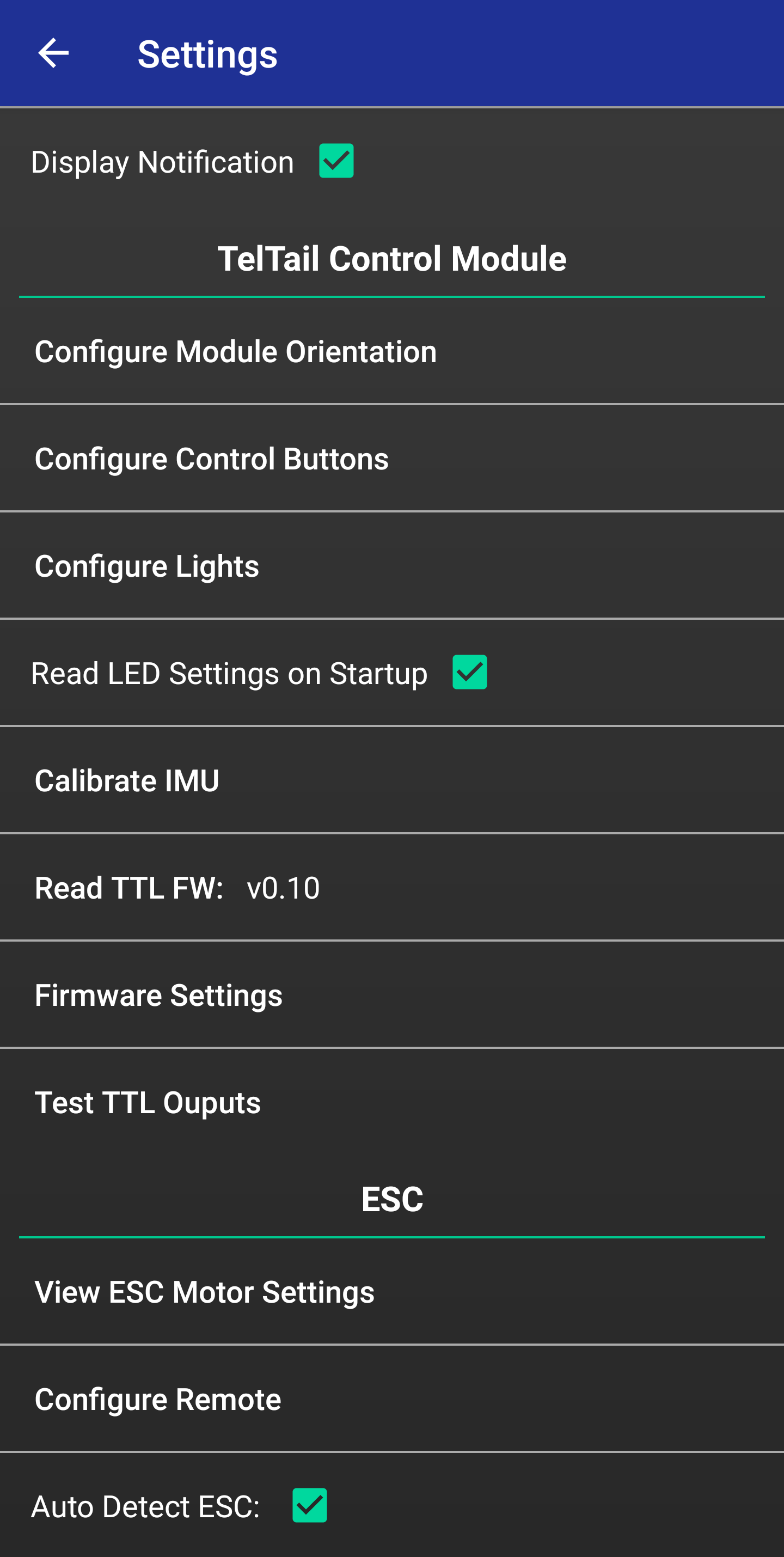
MAIN SETTINGS MENU
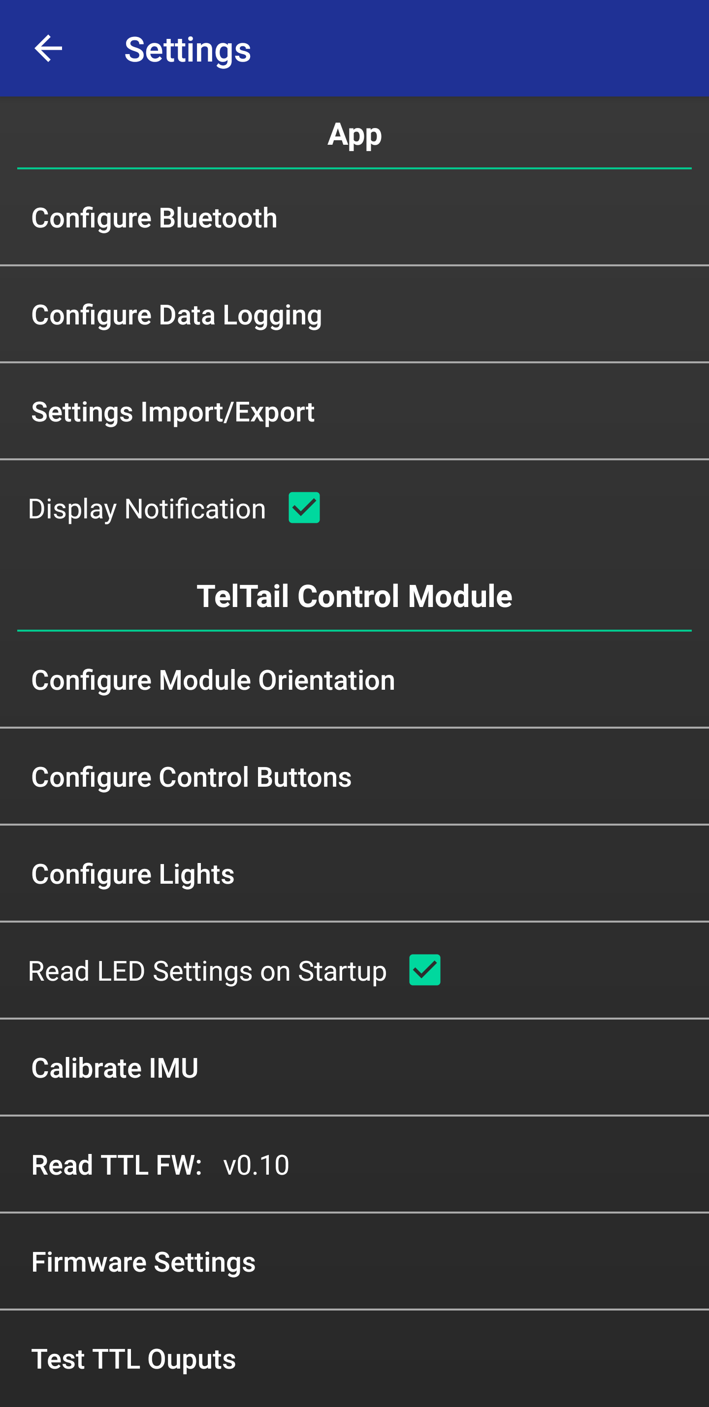
* Display Notification: When checked, a notification will be displayed which provided quick access to certain controls like turning the lights on/off or incrementing/decrementing the light mode
* Read LED Settings on Startup: When checked, the app will read the LED mode settings currently stored on the TTL control module when a Bluetooth connection is established
* Calibrate IMU: When
* Read TTL FW: When
* Test TTL Outputs: When
* Read TTL FW: When
CONFIGURE BLUETOOTH
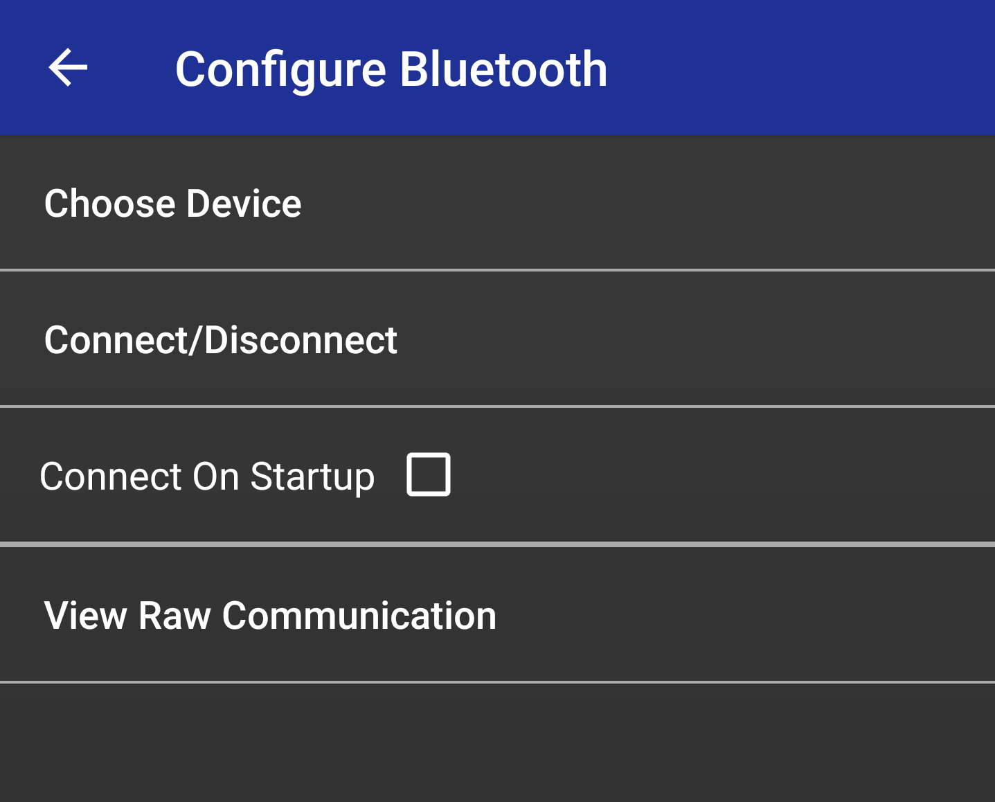
* Connect On Startup: This option, when checked, sets the app to automatically connect to the TTL Control Module when the app is opened
CONFIGURE DATA LOGGING
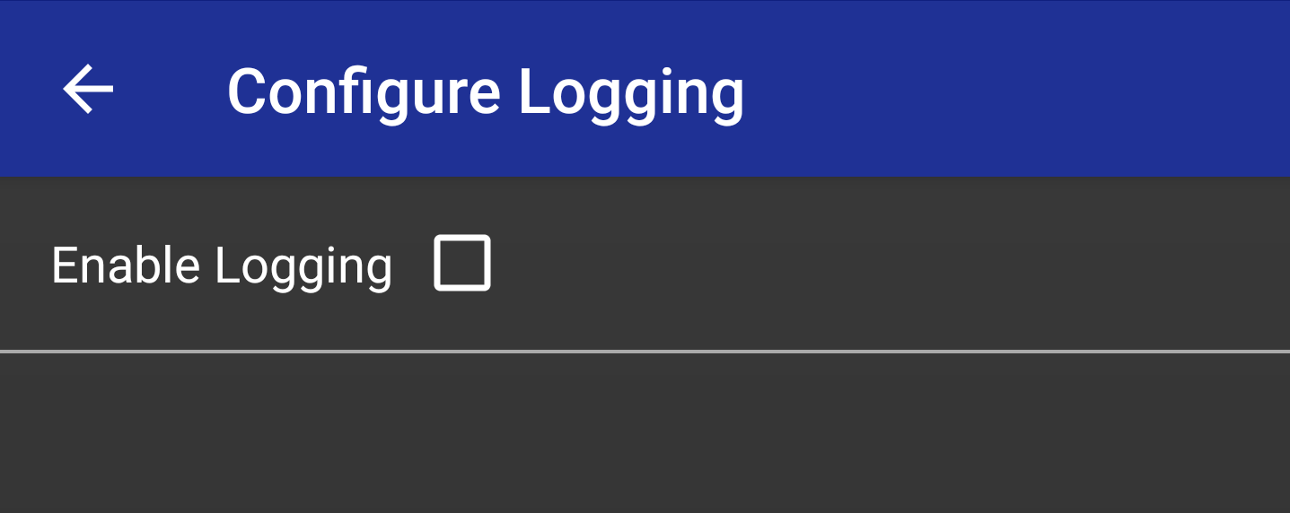
* Enable Logging: This option allows the user to choose whether the data logging buttons are visible in the main app screen and main menu
CONFIGURE MODULE ORIENTATION

* Connectors Orientation: This option sets the orientaion of the module’s axis in line with the connector pins.
* Power Cord Orientation: This option set the orientation of the module’s axis in line with where the power cord exits.
CONFIGURE CONTROL BUTTONS
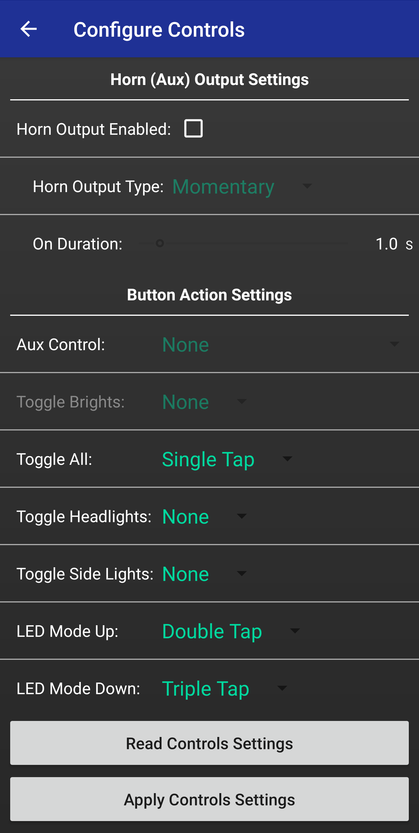
* Horn (Aux) Output Enabled: This option allows the user to enable or disbale the aux output on the TTL Control Module. Control buttons for the aux output will dis/appear depending on the stat of this option.
* Horn Output Type: When the aux output is enabled, this option sets the type of control the user has over the aux output
* On Duration: When the aux output is enabled and “Timed” is selcted as the control type, this option specifies the durationin which the output is kept active after it is commanded
Button Action Settings
* Aux Control: When the aux ouput is enabled, this option sets how the aux output os enabled using the button input on the TTL Control Module.
* Toggle Brights: Sets how the user activates and deactivates the brights (highbeams). The brights need to be enabled in the “Config Lights” menu for this menu option to be configurable.
* Toggle All: Sets how the user interfaces with the remote button to toggle on/off all of the LEDs. (Exclude the aux output)
* Toggle Headlights: Sets how the user interfaces with the remote button to toggle on/off the headlights and tailights.
* Toggle Side Lights: Sets how the user interfaces with the remote button to toggle on/off the RGB side lights.
* LED Mode Up: Sets how the user interfaces with the remote button to cycle “up” through the LED modes.
* LED Mode Down: Sets how the user interfaces with the remote button to toggle on/off the headlights.
CONFIGURE LIGHTS
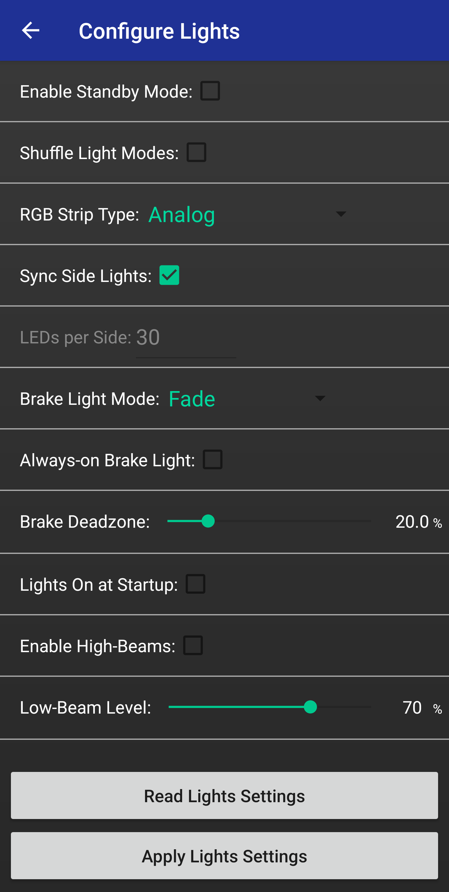
* Enable Standby Mode: When checked, the lights will turn off when the board comes to a stop, and will turn on when the user begins to ride again
* Shuffle Light Modes: When checked, the user will be able to choose all of their favorite light modes to be randomly switched between every 30 seconds
* RGB Strip Type: Sets the type (Analog or Digital) of RGB strips connected to the TTL module
* Sync Side Lights: When unchecked, the side lights will be set to different colors in all light modes
* LEDs per Side: Sets the number of LEDs in each strip of digital side lights (provided strips have 30 LEDs)
* Brake Light Mode: Sets how the brake lights react when the user is braking
* Always-on Brake Light: When checked, the brake light will remain on even when the user command all of the lights off
* Brake Deadzone: Sets the deadzone around the throttle’s midpoint where the brake lights will not react
* Lights On at Startup: When checked, the lights will turn on when the board is first powered on. If unchecked, the lights will remain off on power-up
* Enable High-Beams: When checked, the user can control the headlights to have a high and low brightness state. The control of this state is set in the “Configure Control Buttons” menu and the low level brightness is set below
* Low-Beam Level: Sets the brightness of the headlights when high beams are enabled
FIRMWARE SETTINGS

* Check Latest Firmware on Start: When checked, the app will check that the TTL module’s FW is up-to-date when it establishes a Bluetooth connection
* Choose HW Version Manually: When checked, the user can manually choose the HW version of their TTL module in case the app is not able to correctly read it automatically
* Upload Custom Firmware File: This allows the user to select a custom FW file to upload to their TTL module. The purpose of this is for FW downgrading or uploading test FWs
* Check Current HW & Firmware: Pressing this will cause the app to fetch the currently installed FW on the connected TTL module
* Check Latest Firmware: Pressing this will cause the app to fetch the latest TTL FW
* Update TTL Firmware: Pressing this will begin the process of updating the TTL module’s FW to the latest version
VIEW ESC MOTOR SETTINGS
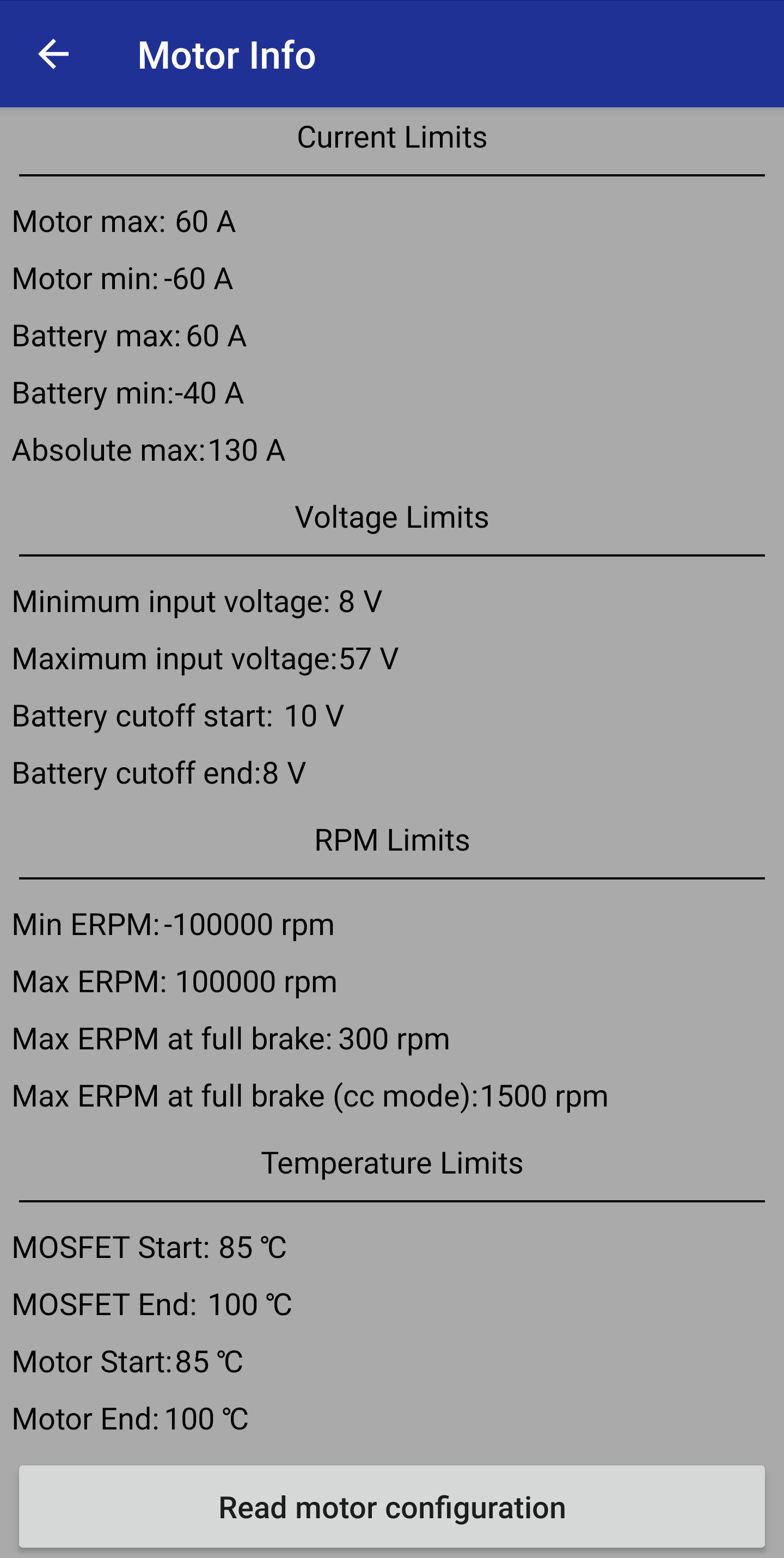
* Read Motor Configuration: This button will read the settings of the ESC and display them in the fields above
CONFIGURE REMOTE
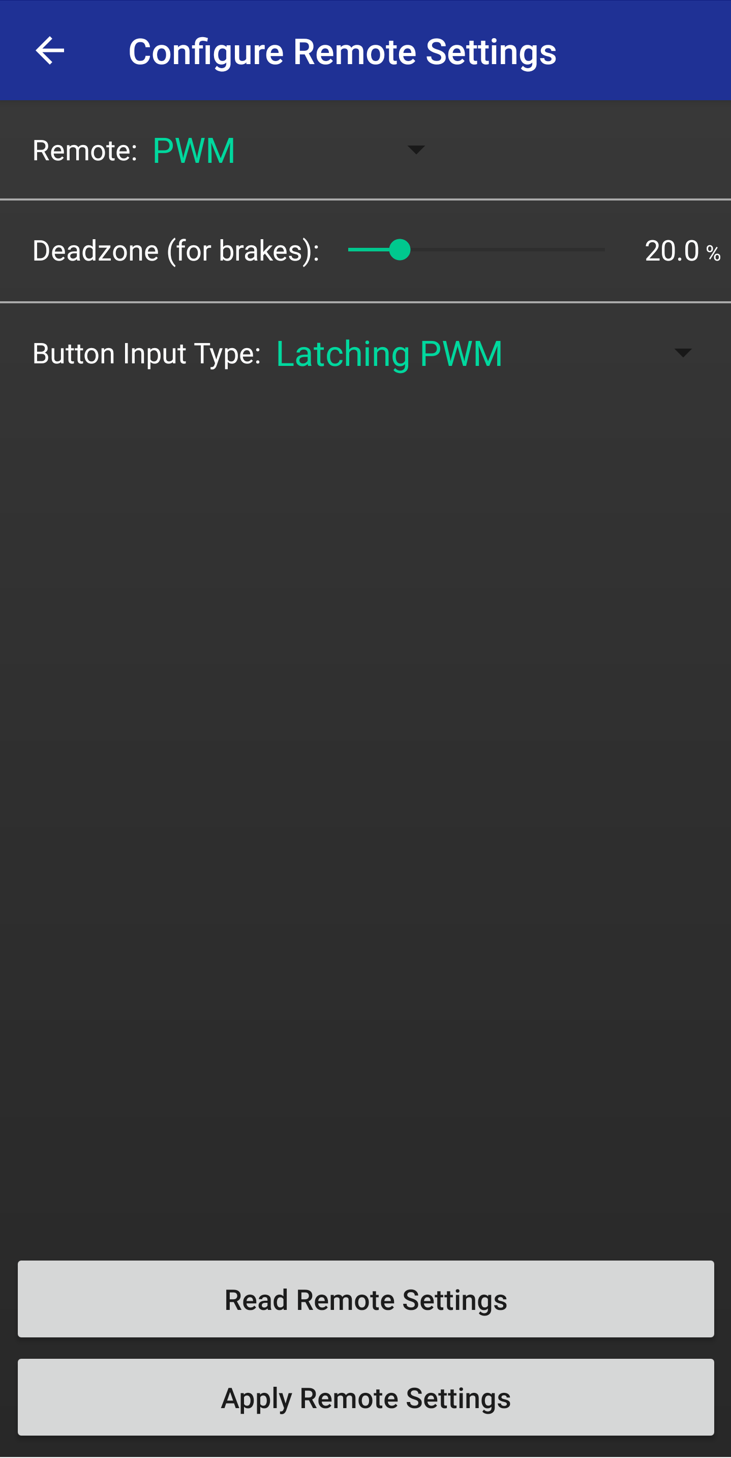
* Remote Type: Sets the type of remote being used in the user’s setup. This is based on how the throttle is communicated to the ESC.
* Deadzone (for brakes): Sets the deadzone around the throttle’s midpoint where the brake lights will not react
* Button Input Type: This sets the type of input signal the TTL module should expect at the button port. This is dictated by the type of remote that the user has.
Button Input Types

* None: For setups without a button input. Completely configures the button controls off.
* Momentary: For remotes (like the TB nano) that have a button mapped to an output that is high when the button is pressed and low when the button is not pressed
* Latching: For remotes that have a button mapped to an output that toggles between high and low whenever it is pressed
* Latching PWM: For remotes (like the GT2B) that have a button mapped to an output that toggles its PWM value whenever it is pressed
* UART (Chuck Struct) C: For remotes that communicate their throttle and button status over UART using the VESC’s Chuck struct. This option is for when the button is mapped to the C button in the chuck struct.
* UART (Chuck Struct) Z: For remotes that communicate their throttle and button status over UART using the VESC’s Chuck struct. This option is for when the button is mapped to the Z button in the chuck struct.
* Throttle Down: For setups without a button input. A flick of the throttle downward (brake) will be registered as a button press
* Throttle Up: For setups without a button input. A flick of the throttle upward (accelerate) will be registered as a button press